
Cathodic protection (CP) reduces corrosion activity by changing the electrical potential of reinforcing steel. The two main approaches are galvanic protection using sacrificial anodes and impressed-current protection using an external power supply. Both require design, electrical continuity and monitoring points; neither replaces investigation of the damage or structural assessment. [1, 2]
Galvanic or impressed current?
In galvanic protection, a less noble anode is electrically connected to the reinforcement. The anode is gradually consumed and no external power source is needed. Available current is limited by the anode, moisture and electrical resistance of the system. This may fit certain limited zones or preventive applications.
In impressed-current protection, a rectifier supplies current through anodes to the reinforcement. Current can be adjusted and divided by zone, but power, cables, reference electrodes, monitoring and maintenance are required. Incorrect settings can be harmful; prestressing steel requires specialist expertise. French Cerema guidance recommends specialist study for prestressed concrete and emphasizes long-term management. [1]
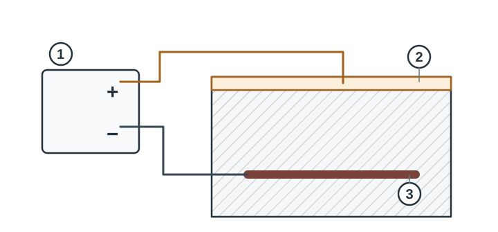 Impressed-current principle. 1. Rectifier. 2. Anode on the positive terminal. 3. Reinforcement on the negative terminal. The monitoring circuit is omitted.
What should the design define?
ISO 12696:2022 covers cathodic protection systems with monitoring that can demonstrate whether the protection criteria are met. It excludes galvanic anodes used in patch repairs to reduce the risk of new anodic areas. [3]
The design needs the damage and chloride picture, electrical continuity, zones, anode locations, power and cable routes, reference electrodes, measurement procedures and an asset-management plan. It sets protection criteria and settings using applicable standards and the structure; the illustration gives no current or potential limits. Prestressed members require separate assessment of risks to the steel and anode system. [1, 2]
Monitoring and maintenance
Keep baseline readings and design settings. Under the monitoring plan, record items such as power, current, reference-electrode response and electrical connections. An alarm, unexpected reading or missing measurement calls for diagnosis; one potential reading alone does not prove that all reinforcement is adequately protected. Sacrificial anodes are consumed and components can fail in either type of system, so access and replacement belong in the maintenance plan. FHWA research describes measurement methods and their limitations. [2]
Ask who designs and commissions the system, how zones and electrodes are located, which readings are logged, who responds to alarms, how replacement parts are maintained and what the owner must manage over time.
See also repair and protect reinforcement, reinforcement corrosion and concrete condition assessment.
Sources
- Cerema, Instruction technique pour la surveillance et l’entretien des ouvrages d’art, Fascicule 32 — Ponts en béton précontraint, 2023, §2.2.4 “Protection cathodique”: galvanic/impressed-current differences, monitoring and specific cautions for prestressed concrete. French asset-management context; do not apply criteria without design. PDF · Cerema publication overview.
- FHWA, Long-Term Effectiveness of Cathodic Protection Systems on Highway Structures, FHWA-RD-01-096, 2001, §§2.2–2.3 and 9.9: measurement setups and limitations for impressed-current and galvanic systems. Report.
- ISO 12696:2022, Cathodic protection of steel in concrete. Official abstract on scope and performance monitoring. ISO.